
 Russian
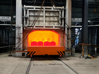
The complete process and key control points for tempering furnace construction (including foundation, furnace body masonry, lining, electrical work, furnace drying, and commissioning) are organized according to the standard practices for industrial furnaces. It is applicable to box-type, pit-type, and trolley-type tempering furnaces.
I. Pre-construction Preparation
1.Technology and Documentation
- Drawing Verification: Check the general drawing of the furnace body, masonry drawing, electrical schematic diagram, foundation drawing, and pipeline layout drawing.
- Specification Basis: Refer to standards such as GB51059, JB/T3649, JB/DQ5071, etc.
- Material Inspection: For refractory bricks (high-alumina and lightweight), refractory fibers, castables, insulation materials, electric heating elements, furnace shell steel plates, etc., they should have certificates of conformity and be re-inspected.
2. Site and Foundation.
- Environment: The construction site should be dry, well-ventilated, free of corrosive gases and dust, and far away from vibration sources.
- Foundation:The concrete strength should be ≥ C20, the flatness should be ≤ 3mm/m, and the levelness should be ≤ 2mm/m.Reserve anchor bolt holes, cable trenches, sewage and drainage slopes.After the curing period, the bearing capacity should meet the equipment requirements, and there should be no cracks or settlement.
3. Equipment and Safety
- Equipment: Prepare welding machines, cutting machines, winches, vibrators, levels, thermometers, megohmmeters, etc.
- Safety: Obtain fire-starting approvals, prepare fire - fighting equipment, provide insulation protection, protection for high-altitude operations, and ventilation and dust-removal facilities.
II. Furnace Shell Fabrication and Installation
1. Cutting and Welding
Use Q235 steel plates and section steels (channel steel, angle steel) to weld the framework and reinforce it with stiffeners. The welds should be continuous, free of air holes, and the deformation should be corrected.
2. Furnace Shell Assembly
- Hoist the furnace shell in sections or as a whole, level and align it, with the verticality ≤ 3mm/m.
- Weld the furnace door frame, guide rails, and sealing grooves in place to ensure the furnace door closes tightly.
3. Pre-installation of Accessories
Open and reinforce holes for the furnace door, observation holes, temperature-measuring holes, explosion-proof ports, material inlets and outlets, etc.
III. Refractory Lining Construction (Core)
1. Furnace Wall Masonry (from the inside out)
- Inner Layer: Use lightweight high-alumina bricks and refractory bricks, lay them in a staggered pattern with a mortar joint ≤ 2mm and ensure the mortar is full.
- Middle Layer: Lay aluminum silicate fiber felts and fiber modules in a staggered layer pattern with a compression rate of 10%-15% and fix them with insulation nails.
- Outer Layer: Fill with insulation bricks and perlite fillers tightly to reduce heat loss.
Use the centerline of the furnace chamber as the reference, start from the inside and work outwards, lay bricks in a staggered pattern without through-joints. The bricks at the furnace mouth, burner holes, and temperature-measuring holes should be processed accurately.
2. Furnace Bottom Construction
- Base Layer: Level the steel plate and lay asbestos boards and insulation bricks.
- Working Layer: Use heavy-duty high-alumina bricks, either dry-lay or wet-lay them in a staggered pattern. The furnace bottom should slope towards the drainage outlet (1%-2%).
3. Furnace Top Construction
- Suspended Type: Suspend refractory fiber modules and lightweight bricks, weld the anchors firmly, and reserve thermal expansion gaps.
- Arch Type: Lay wedge-shaped bricks in a staggered pattern, fix the arch springer bricks, and ensure the mortar joints are tight.
4. Installation of Burners and Heating Elements
- Resistance Wires and Radiation Tubes: Install them after the lining is completed, ensure proper insulation support and leave enough expansion gaps.
- Burners: Install them in the correct position, connect them firmly without jamming, and ensure tight sealing.
5. Construction of Unshaped Refractory Materials (Casting and Ramming)
- Mixing: Add water according to the proportion, mix evenly without segregation.
- Construction: Set up formwork→pour and ram→cure. The curing period should be ≥ 24h (at room temperature), and avoid watering too quickly.
IV. Electrical and Pipeline Installation
1. Electrical System
- Wiring: Separate power and control cables, protect them with conduits, and ensure the insulation resistance is ≥ 0.5MΩ.
- Temperature Control: Install thermocouples (Type K/S) correctly, connect the compensation wires correctly, and commission the temperature control cabinet, recorder, and alarm device.
- Grounding: Ensure the furnace shell, electrical cabinet, and motor are reliably grounded, with the grounding resistance ≤ 4Ω.
2. Gas and Air Circuits (Gas and Hot-air Circulation)
- Pipelines: Use seamless steel pipes, connect them by welding or flanges, and conduct air-tightness tests (0.6MPa, hold for 30min without leakage).
- Valves: Install regulating valves, safety valves, and vent valves in place, and ensure they open and close flexibly.
V. Furnace Drying (Necessary to Prevent Cracking)
Furnace Drying Curve (for newly built furnace linings)
1. From room temperature to 200°C: 2-8h (open the furnace door to remove moisture).
2. From 200°C to 400°C: 2-8h (slightly open the furnace door).
3. From 400°C to 600°C: 2-6h (close the furnace door).
4. From 600°C to 800°C: 2-6h.
5. From 800°C to 900°C: 2-6h.
Key Points
- The heating rate should be ≤ 50°C/h, and rapid heating is strictly prohibited.
- After the furnace drying is completed, cool down to below 100°C and measure the insulation resistance ≥ 0.5MΩ.
VI. Commissioning and Acceptance
1. No - load Commissioning
- Mechanical Part: The lifting of the furnace door, the movement of the trolley, and the operation of the transmission system should be smooth, without jamming or abnormal noise.
- Electrical Part:The temperature control accuracy should be±5°C, and the over-temperature alarm and interlock protection should work normally.
- Air-tightness: There should be no air leakage at the furnace door, flanges, and welds.
2. Load Test Run
Heat up according to the process (e.g., 550-650°C) and hold for 2-4h, then check:
- Furnace Temperature Uniformity: ≤ ± 10°C (measure the temperature in different zones).
- Furnace Lining: There should be no cracking, falling off, or deformation.
- Equipment: The equipment should operate normally without abnormal vibration or odor.
3. Acceptance Documentation
Prepare material certificates of conformity, concealed work records, furnace drying curves, commissioning reports, and as - built drawings.
VII. Common Problems and Prevention
- Furnace Lining Cracking: Caused by improper furnace drying, rapid heating, or insufficient expansion gaps. Solution: Strictly follow the furnace drying curve and leave enough gaps.
- Poor Insulation: Caused by non-full mortar joints, insufficient fiber compression, or poor sealing. Solution: Lay bricks in a staggered pattern, compress the fibers properly, and ensure tight sealing.
- Inaccurate Temperature Control: Caused by improper installation of thermocouples, incorrect connection of compensation wires, or drift of the temperature controller.
Solution: Install and wire correctly, and calibrate regularly.
